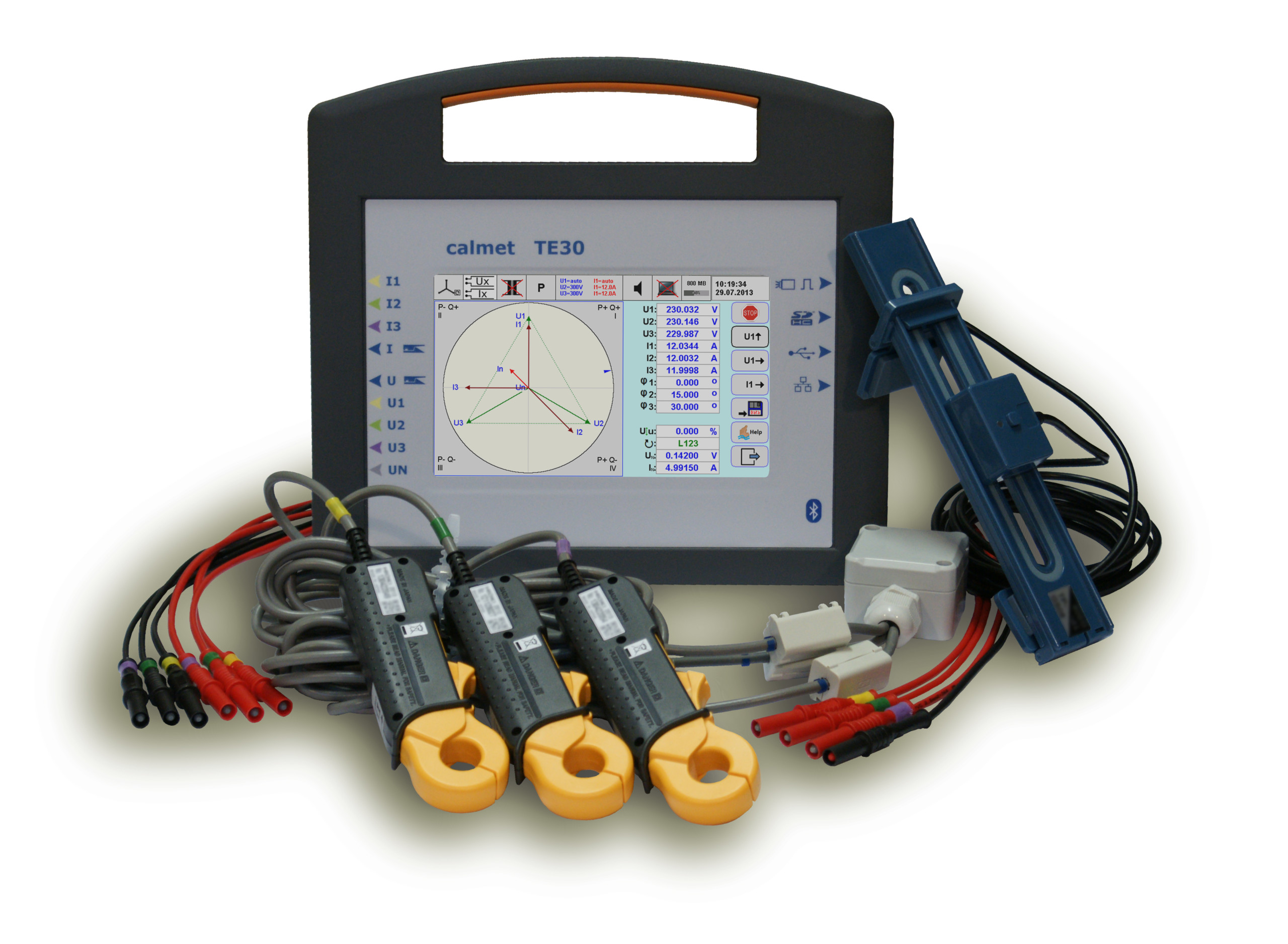
TE30 Three-Phase Network Analyser and Tester of Electricity Meters and Instrument Transformers
- Measure of power network parameters in class 0.05 or 0.1
- Voltage ranges 0.05…600V and 0.1…40KV
- Current ranges 0.001…12(120)(1200)(30/300/3000)A
- Testing of electricity meters and CT/PT Transformers
- Recording and analyze of power quality
- Vector, oscilloscope, bar and trend charts of three phase network
- Powering from 50…450V AC power network and internal battery with charger
- Large 7" color Touchscreen
- Data readout and meter control via USB, Ethernet and Bluetooth
- Data storage in SD flash memory card up to 32GB
The TE30 Analyser and Tester is used for:
- verification of power network wiring with measure and recording of power network parameters,
- calibration and testing of electricity meters and instrument transformers (CT Current Transformers and PT Potential Transformers) directly on site
- measuring, recording and analyzing of power quality.
Large Touchscreen with display and keyboard functions for easy operation enables:
- measure of power network parameters: voltages U1, U2, U3, U12, U23, U31, UN; currents I1, I2, I3, IN; frequency; phase angles φ1, φ2, φ3; power factors PF1, PF2, PF3, ΣPF; factors sinφ1, sinφ2, sinφ3, Σsinφ, tgφ1, tgφ2, tgφ3, Σtgφ; angles between voltages U12, U23, U31; powers P1, P2, P3, ΣP, Q1, Q2, Q3, ΣQ, S1, S2, S3, ΣS
- visualization of measurement results in form of table, vectors, trend chart, oscilloscope (waveform) or bar chart (harmonics of U, I, P, Q).
Testing of electricity meters directly on site:
- function of calculating meter error (partial errors, average error, standard deviation) directly in [%] with method of settings time of measurements or number of impulses,
- function of automatic identification meter constant,
- function of automatic determining measurement time or number of pulses,
- function of measuring energy with method of setting time for verification of meter counters directly in [%],
- function of maximum power measuring for testing of maximum power meters,
- visualization in form of table or trend chart,
- function of measuring energy for power P, P+, P-, Q, Q+, Q-, S,
- function of measuring energy for the first harmonic of active power PH1.
Testing of instrument transformers (LV and MV current CT and potential PT simultaneously in three phases) directly on site:
- functions of calculating transformer ratio error directly in [%],
- functions of calculating phase error,
- functions of burden measurements of transformer.
Power quality analyser function enables:
- measuring of power quality parameters according to IEC 61000-4-30 class A with visualization of measurement results in the real time mode,
- recording of power network parameters in the SD Flash 4-32GB memory, which gives (8..64)x106 sets of network parameters or long-term registration of power quality (option),
- analyzing of measurement results for EN 50160 compatibility or individual requirements of user (option).
| POWER NETWORK ANALYZER | ||||
| Parameter | Range | Error limits (1)(2)(3)(4) | ||
| class 0.05 | class 0.1 | |||
| Voltage (Direct) | 0.05…600V | ±0.05% (5) | ±0.1% (5) | |
| Voltage (VoltLiteWire 40kV) | 0.1…40kV | ±0.1%±Em | ||
| Current Direct connection | 0.01…12A 0.001…0.01A | ±0.05% ±0.05%* | ±0.1% ±0.1%* | |
| Current thru clamps CT10AC/ Clamps CT100AC/ Clamps CT1000AC | 0.1…12A / 0.1…120A / 10…1200A 0.003…0.1A / 0.01…0.1A / 0.3…10A | ±0.2% ±0.2%* | ||
| Current (Flexible Clamps FCT3000AC) | 0.3…30A/3…300A/30…3000A | ±0.1%±Em | ||
| Current (AmpLiteWire 2000A) | 30…2000A | ±0.1%±Em | ||
| Power and energy (Direct) | 0.01…12A / 10…600V | ±0.05% | ±0.1% | |
| 0.001…0.01A/10…600V | ±0.05%* | ±0.1%* | ||
| Power and energy (Clamps CT10AC) | 0.1…12A / 10…600V | ±0.2% | ||
| 0.01…0.1A / 10…600V | ±0.2%* | |||
| Power and energy (Clamps CT100AC) | 0.1…120A / 10…600V | ±0.2% | ||
| 0.01…0.1A / 10…600V | ±0.2%* | |||
| Power and energy (Clamps CT1000AC) | 10…1200A / 10…600V | ±0.2% | ||
| 1…10A / 10…600V | ±0.2%* | |||
| Power and energy (Flexible Clamps FCT3000AC) | 0.3…30A/3…300A/30…3000A / 10…600V | ±0.1%±Em | ||
| Power and energy (VoltLiteWire 40kV + AmpLiteWire 2000A) | 30…2000A / 0.5…40kV | ±0.1%±Em | ||
| Frequency | 40…70Hz | ±0.01Hz | ||
| Phase shift (Direct) | -180…+180° | ±0.02° (5)(6) | ±0.04° (5)(6) | |
| Phase shift (Clamps) | -180…+180° | ±0.1° (5)(7) | ||
| Power factor cosφ and sinφ | 0…±1 | ±0.001(5)(6)(7) | ||
| Temperature coefficient (Direct) | 0.005% per 1°C in range -10…+50°C | |||
| Time stability (Direct) | Short term [1h] = 0.01%, long term [1 year] = 0.03% | |||
| GENERAL PARAMETERS | |
| Weight and dimensions (width x height x depth) | 2kg (with internal battery) and (270x245x90)mm |
| Power supply | 50…450V / 47...63Hz / 15VA or replaceable batteries Ni-MH 5xAA 1.2V / 2600mAh / 2h |
| Safety: Isolation protection and Measurement Category | IEC 61010-1 and 300V CAT III |
| Degree of protection | IP-40 (device) / IP-67 (ET30 transportation case) |
| Operation / storage temperature | -10…+50°C / -20…+60°C |
| Operation / storage relative humidity | <90% @ +0...+30°C and <75% @ +30...+50°C / <95% @ 0...+50°C |
| AUTOMATIC TEST OF ELECTRICITY METERS | |||
| Parameter | Voltage and current range | Frequency range | Resolution |
| Input impulses | 0...2V/4...30V | 0.000001Hz…200kHz | 0.0001%@t≥1s |
| Impulse Output for TE30 testing (8) | 28V/100mA open collector | 0.0001Hz…210kHz | |
| BURDEN MEASUREMENT OF CT AND PT TRANSFORMERS | ||||||
| Parameter | Current range | Voltage range | Error limits (1)(2) | |||
| CT Burden | 0.01…12A (Direct) | 1…10V (Direct) | ±0.2% | |||
| 0.05…1V (Direct) | ±0.2%* | |||||
| PT Burden | 0.01…12A (Direct) | 10…600V (Direct) | ±0.1% | |||
| 0.001…0.01A (Direct) | 10…600V (Direct) | ±0.1%* | ||||
| RATIO MEASUREMENT OF CT AND PT TRANSFORMERS | |||||
| Parameter | Primary current/voltage range | Secondary current/voltage range | Error limits (1)(2)(3) | ||
| CT Ratio | 0.2…120A (Clamps CT100AC) | 0.01..12A (Direct) | ±0.2% | ||
| 0.001..0.01A (Direct) | ±0.2%* | ||||
| CT Ratio | 10…1200A (Clamps CT1000AC) | 0.01…12A (Direct) | ±0.2% | ||
| CT Ratio | 0.3…30A/3…300A/30…3000A | 0.01…12A (Direct) | ±0.1%±Em | ||
| CT Ratio | 30…2000A (AmpLiteWire 2000A) | 0.01…12A (Direct) | ±0.1%±Em | ||
| PT Ratio | 0.5…40kV (VoltLiteWire 40kV) | 10…600V (Direct) | ±0.1%±Em | ||
| POWER QUALITY PARAMETERS | ||||
| Parameter | Range | Error limits (2) | ||
| Harmonics in voltages, currents, P and Q powers | amplitude | 0…100% of input | 1st…63rd | ±0.1% (9) |
| phase | -180…+180° | 1st…63rd | ±0.5° (10) | |
| Total harmonic distortion THD in voltages and currents | 0…100% of input | 1st…63rd | ±0.1% (9) | |
| Total inter-harmonic distortion TID in voltages and currents | 0…15% of input | 40…3200Hz | ±0.2% (11) | |
| Signal voltage (5) | 0…15% of input | 40…3200Hz | ±5% | |
| Flicker Pst and Plt (option) | 0…40 | 0.000833…33.33Hz | ±5% | |
| Voltage asymmetry | 0…100% | ±2% | ||
(1) % – related to the measuring value, %* – related to the measuring range final value (is underlined)
(2) error limits include reference standard uncertainty, 12 mo. stability, influence quantities (ambient temp. +20…+26°C, humidity, power supply 50…450V, freq. 45…65Hz)
(3) Em – sensor basic error, Em=1%+0.1%* (Flexible Clamps FCT3000AC), Em=2%+0.2%* (VoltLiteWire 40kV and AmpLiteWire 2000A)
(4) power and energy errors related to apparent power
(5) in voltage range 10…600V (Direct)
(6) in current range 0.01…12A (Direct)
(7) in current range: 0.1A…12A (Clamps CT10AC), 0.1A…120A (Clamps CT100AC), 10A…1200A (Clamps CT1000AC)
(8) Programmable constant of Impulse Output – preferred value: C = 30 000 [imp/Wh(varh,Vah)]
(9) of input for 80-140Hz frequency range of harmonics with linear rise to 0.4% of input for 3200Hz
(10) for 80-140Hz freq. range of harmonics with linear rise to 8° for 3200Hz of input for 80-140Hz freq. range of inter-harmonics with linear rise to 5% of input for 3200Hz
(11) the highest non-harmonic amplitude and frequency
| Product card | |
 English English |
|